

This thing has been all over the world and has had the crap kicked out of it. The eyes were knocked out, battery cable torn out, at some point someone installed a speaker system inside it attached to an iPod. Its on its last legs after three years of game conventions and parties, so they're after a replacement.
Re-imagined plans:
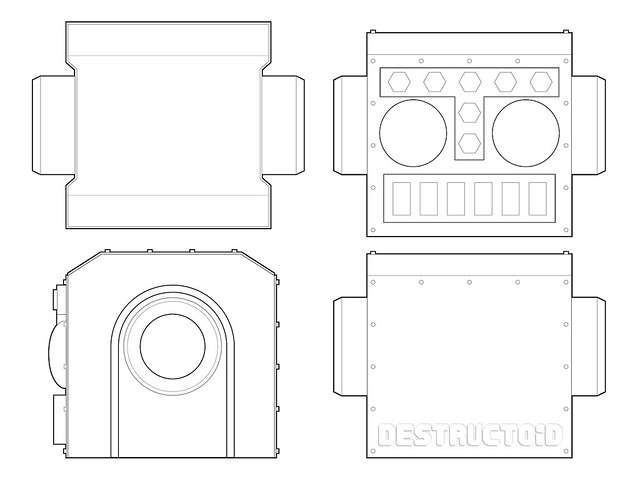
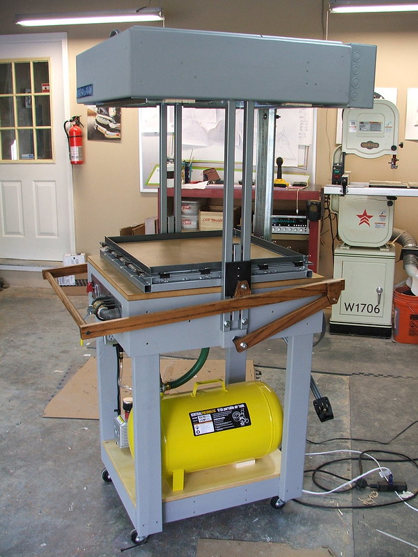
If you're a regular reader of this blog, you might recall the Proto-Form Vacuum forming machine I built a few months ago. That machine was constructed specifically for this project! The large scale of this helmet combined with the thickness of the materials I'd need to be working with meant a new higher-end vacformer was in order. It definitely lived up to expectations, and has been a very valuable addition to my shop.
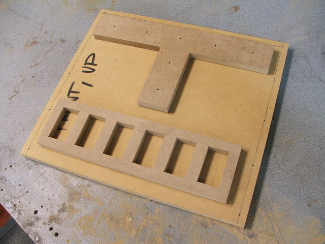
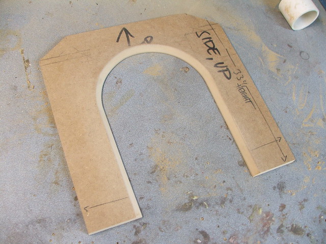
I started off by making some of the simpler forms from sheets of MDF. The faceplate and side panels were layered 1/2" sheets with accent pieces cut to shape on a scroll saw. Since the side panels are symmetrical from left to right, I would only need to make one of these bucks in order to pull copies for both sides.
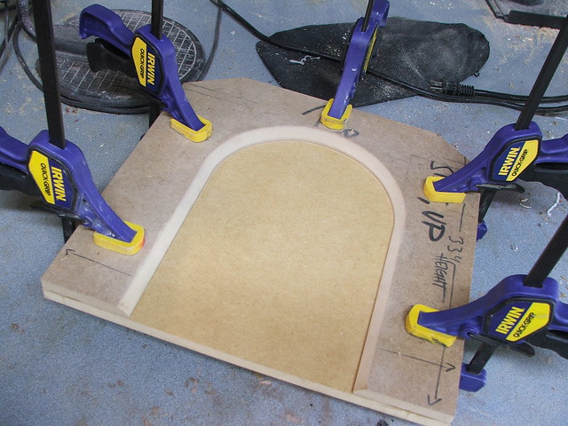
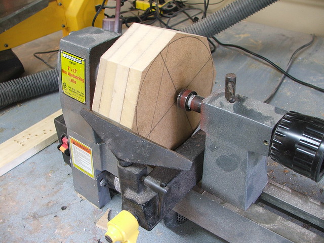
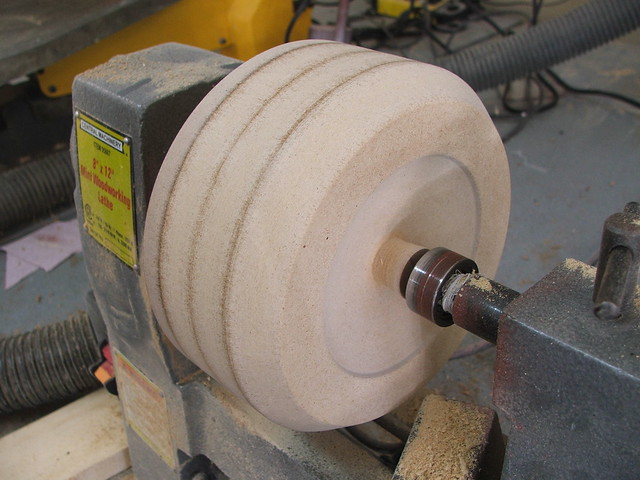
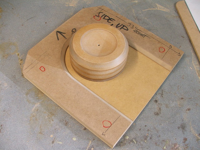
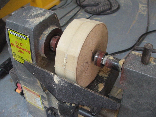
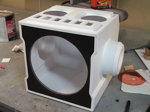
The large ear puck started out as a 2" thick chunk of MDF, rough cut into an octagon before being turned on a lathe. The final piece has a hole drilled through the center in order to allow air to be pulled into the large divot during vacuum forming.
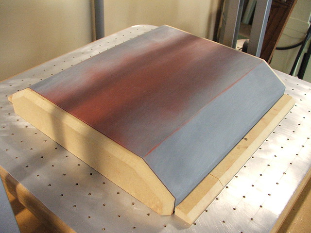
The top of the helmet would be a bit too thick to make out of a solid brick of wood, so I started by making a set of MDF spines that would have 1/4" secured to it with brad nails.
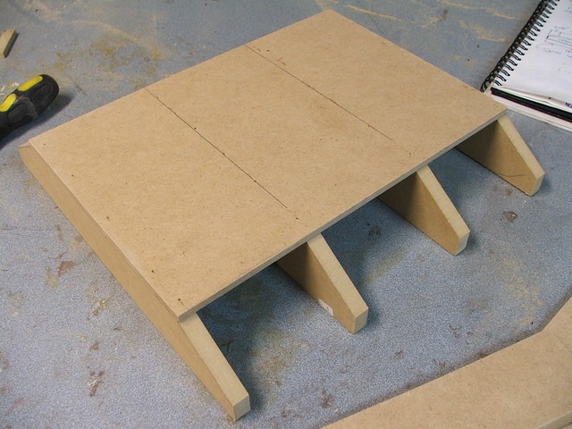
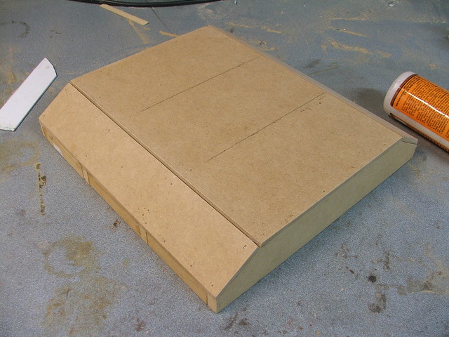
After the outer "skin" was completed, I filled the interior cavity with expanding foam to make sure the vacuum of the machine wouldn't crush the thinner wood.
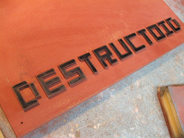
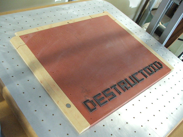
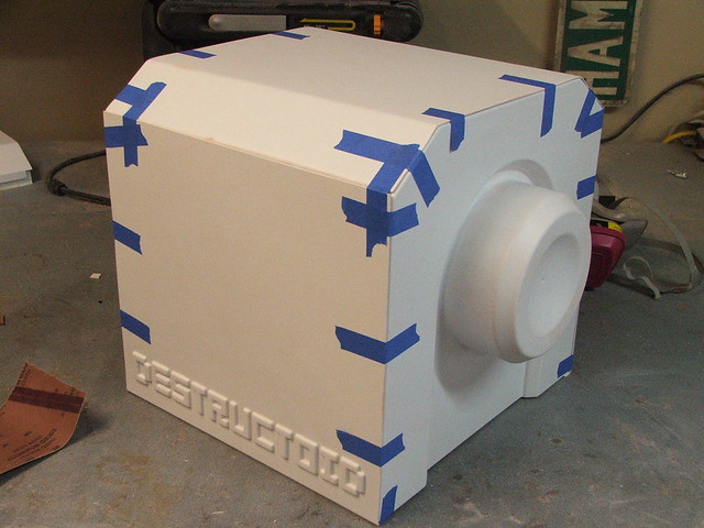
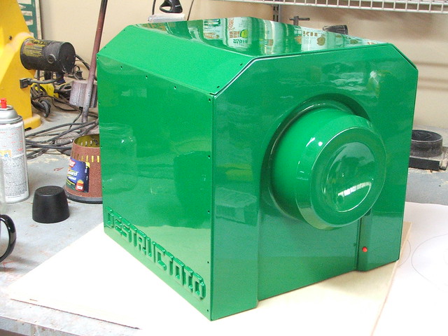
The backside of the old helmet had a riveted strip at the top, similar to the eyebrow section on the front. Mostly this was just to add some visual interest, but for the new one I thought adding the Destructoid name to the plastic would be a much more interesting look. The guys at Destructoid supplied me with their font, and I cut the logo out of 1/8" acrylic on my laser cutter.
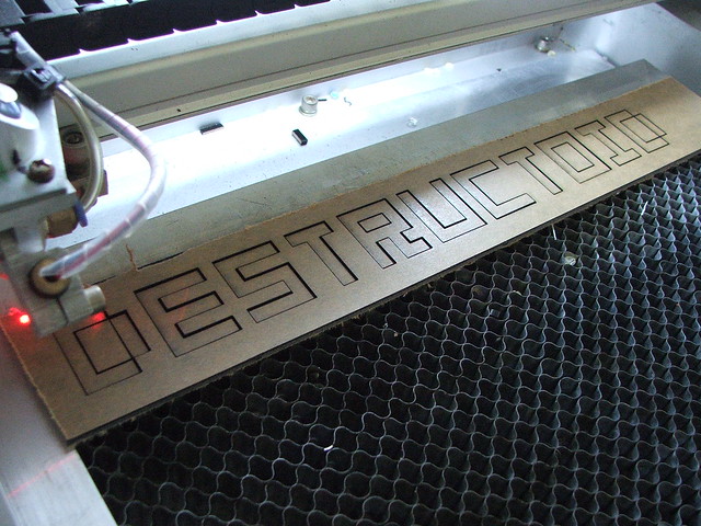
Using the negative space as a frame for the new letters, the acrylic was glued to the back side buck. I had to drill small holes in the corners of some of the letters to make sure the air would be sucked through them to give me a nice detailed pull.
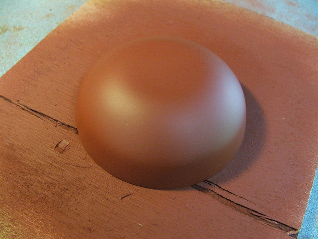
The last buck that needed to be made was for the large eye lenses. This, again, started as a couple laminated pieces of MDF. After a bunch of turning, sanding and filling, I had a smooth pretty dome.
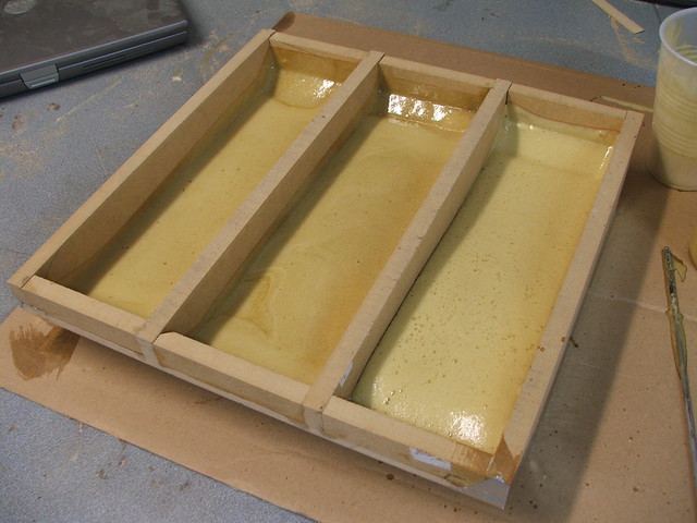
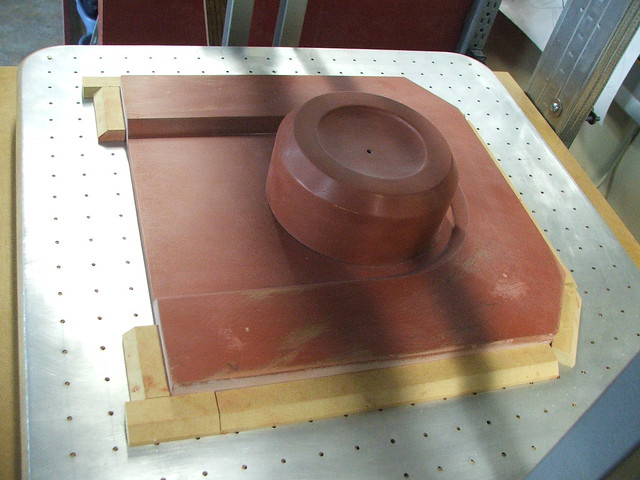
Onto the forming… almost! Before this, I made a series of drafts for the forms out of 1/2" MDF. Pieces like these make it much easier to remove the finished part from the van formed plastic, and also make sure that you don't get a lot of nasty webbing along your corners. I made these parts in several different lengths so the same set could be used for all the parts. The upper section of the helmet needed two large custom blocks made for the sides, however.
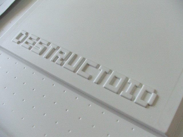
Plastic time! All of these parts were pulled from .10" styrene. The detail I got on the letting was VERY impressive. I really love this new machine.
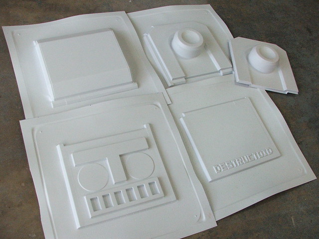
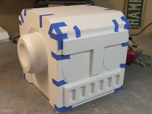
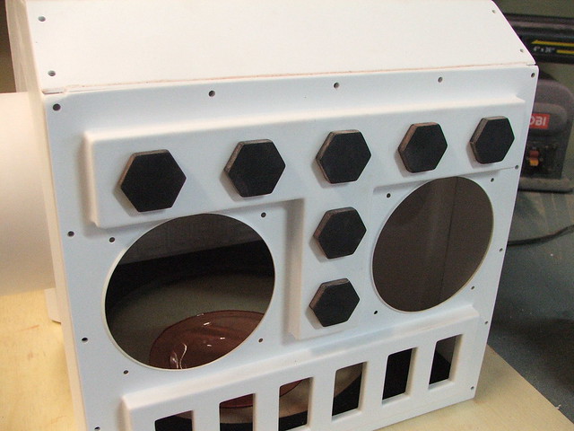
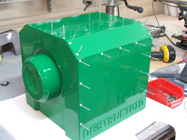
After trimming, I taped all the pieces together to see how things were shaping up. Pretty much exactly as I'd imagined, thankfully.
The eye pucks were pulled out of 1/16" PETG plastic, on my old smaller vacuum forming machine. The wire grid there ensures you still get vacuum even if all the holes are blocked with plastic.
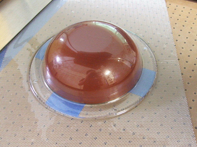
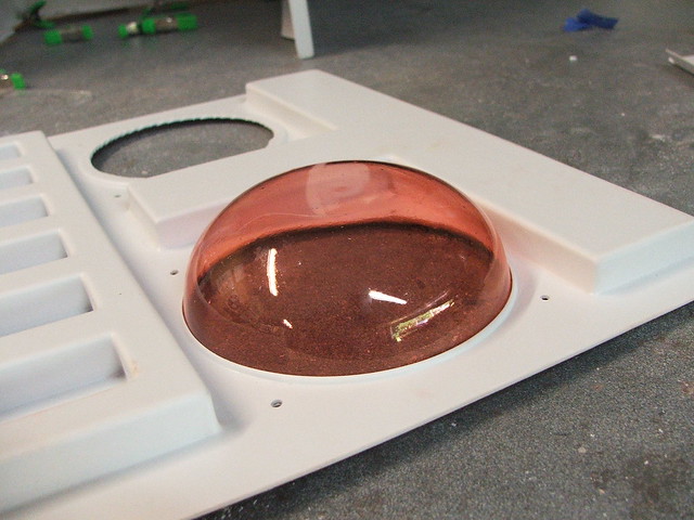
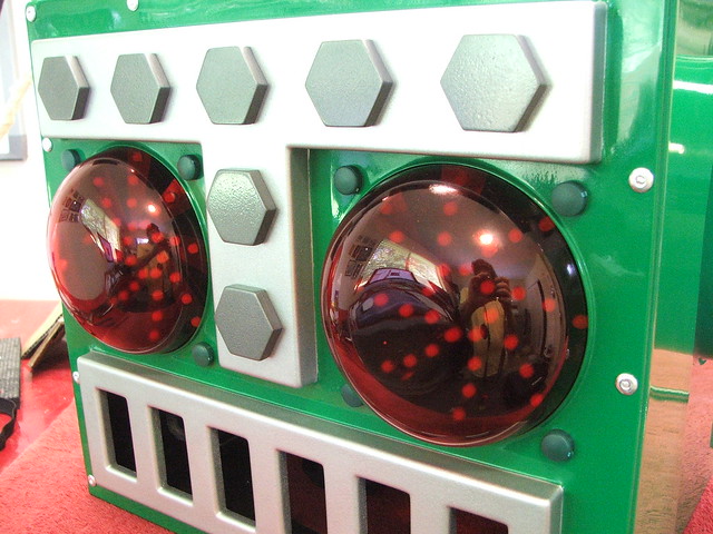
These clear parts were then dyed red with a material called "iDye Poly" I had one test piece, shown here, that I used to check fitment of the eye areas. I'd like to claim that that fine edged lip in the faceplate was entirely intentional, but it was just a very fortunate accident that happened to look cool!
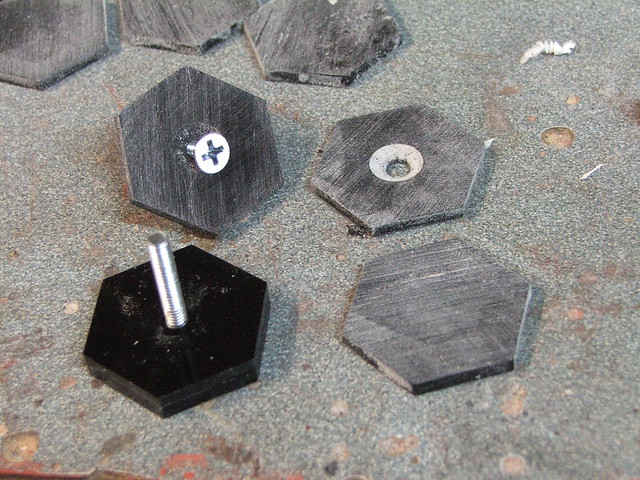
The large bolt heads were trimmed from 1/8" acrylic, and had a screw embedded in between their two halves to secure them to the helmet faceplate. The longer threads of the screws came in handy later when I was routing wiring around inside there; they allowed me to use some wire C-clamps and additional nuts to make sure all the wiring was clean and tidy.
At the base of the helmet, I added a reinforcing plate made out of 3/8" sintra. This plate would eventually be the mounting plate for all of the electronics and wiring for the eyes.
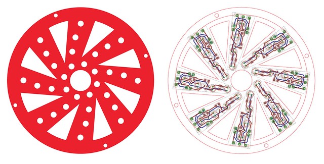
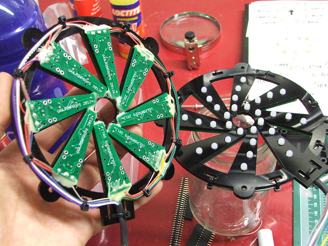
Speaking of wiring, it was at about this time that my circuit boards showed up. The boards for this project seem overly complicated, and they kind of are. I would have much rather made the entire "eye" board out of one PCB, but unfortunately the software I work with (Cadsoft's EAGLE layout editor) has a small working area on the free version, so I had to come up with a different solution. Each segment of the eyes would be its own separate board, and these would all need to be wired together for power, ground and signal. More complicated, yes, but it works!
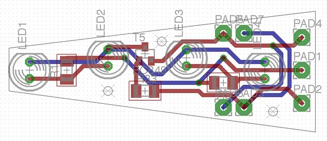
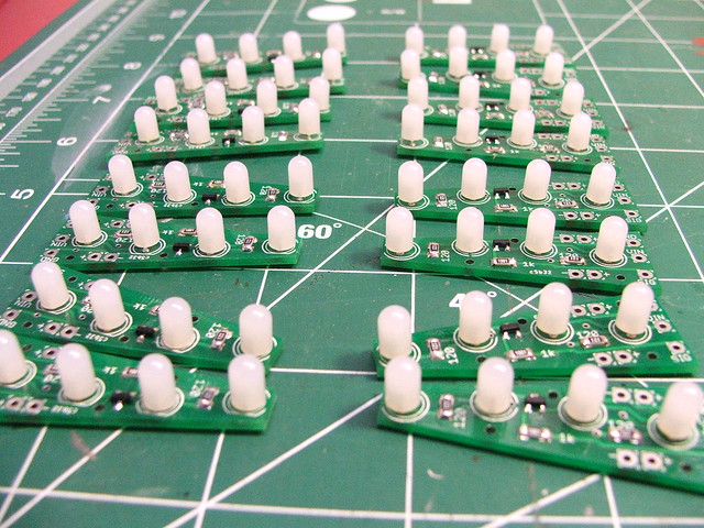
The soldered boards. Using SMD components helped me keep these fairly small, and the frosted red LEDs have a very nice full 180º viewing angle. Boards were printed at BatchPCB.com
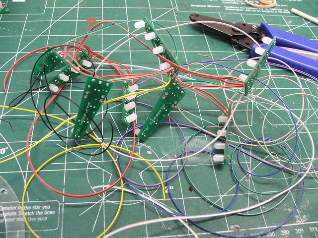
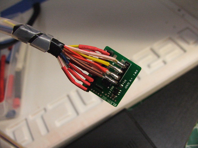
Wiring was… messy for the first few passes.
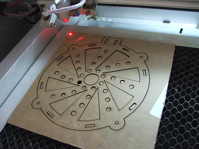
Here's the LED holder being cut on my laser (I'm a bit spoiled with this thing, I know…)
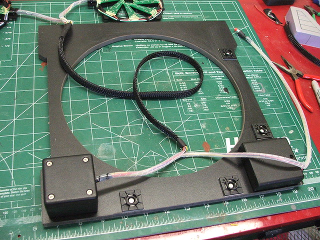
And the assembled eye lighting rigs. There are holes cut in these to help the wearer have a bit more vision out of the helmet than in previous models. In the old helmet, you could only look out of the mouth section. While the LEDs reflecting against the lenses does make looking out of the eyes a tad difficult, it's better than having a big solid wall in front of your face!
First test fire!
This is the little brain chip that makes all the animations possible. This was created by a very talented electronics guru, Donnie James. There are tons of animation sequences this little chip can do, and this helmet has about 20 patterns programmed into it. If you'd like to order your own, you can find a link to his products here.
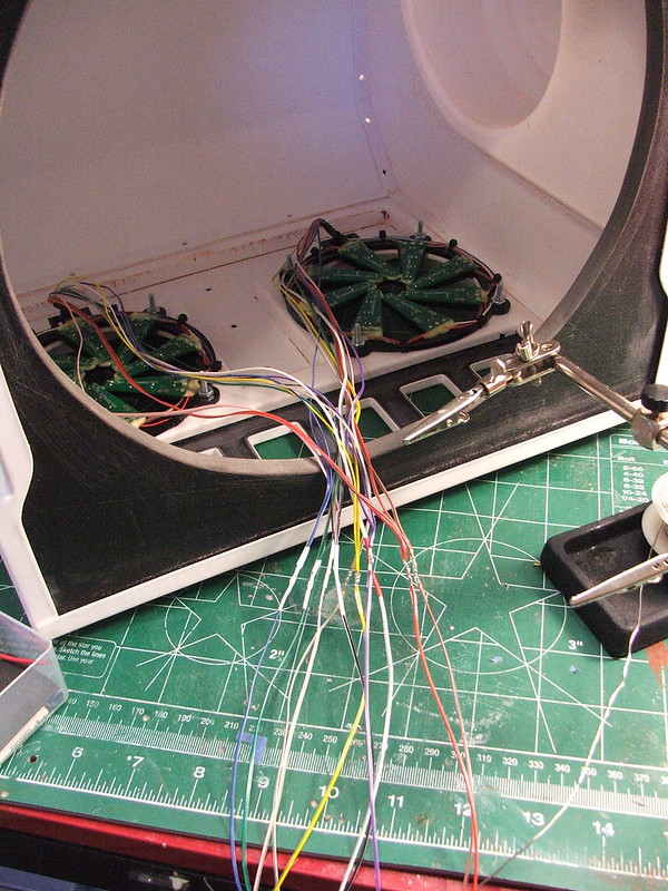
More wire mess.
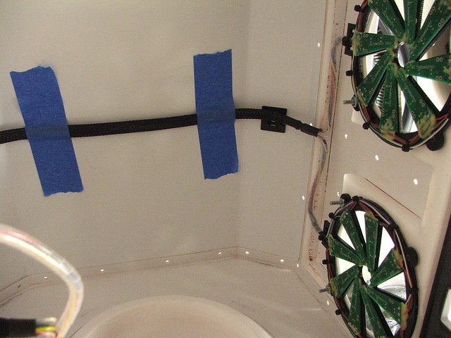
The eyes installed!
After a lot of wire wrap, zip ties, and conduit mounts, things start to look cleaner inside the helmet. I guess it's a hold over from my days doing car audio installation, but I have a sort of mania about wires being clean and routed properly.
The baseplate section with the brain box installed (lower left) and battery tray (lower right.) The helmet runs off 4 AA batteries and should get about 20 hours of life out of one set.
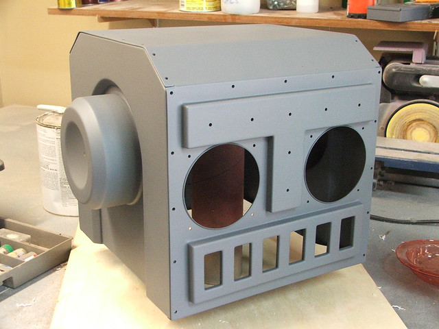
Onto paint! The assembled helmet was stripped of all the electronics and internals, leaving me with a blank shell that got a couple coats of primer. The helmet right now is just held together with superglue around the seams, but this will be strengthened later after paint with some rivets along the various holes you can see here. I really recommend anyone doing projects like these to install all your mounting points and drill all your holes before you put the final paint coat on the project you're building. The likelihood of scratching a nice finish when you're trying to figure out how to mount a component is too high - I know I've done it!
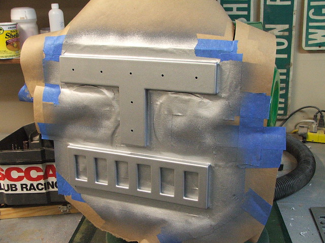
Silver accents being masked off on the faceplate.
The green paint was sprayed quite thick, then allowed to cure for 7 days. After this, the entire helmet was wet sanded down to 2000 grit sandpaper.
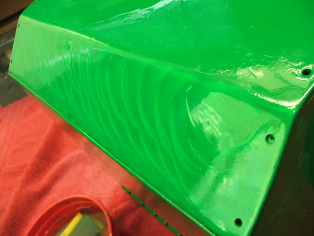
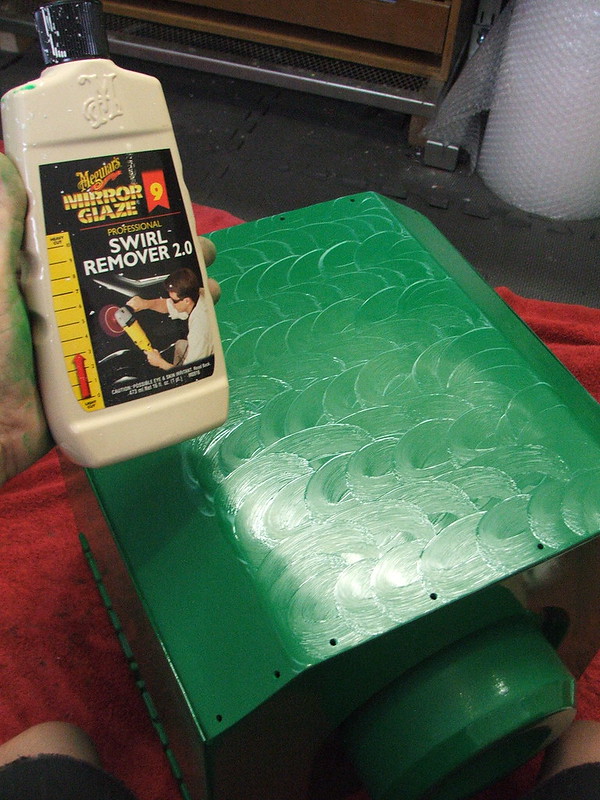
After the wet sanding, the entire piece was buffed with swirl remover, then given 5 coats of Meguiar's Tech Wax. The results are very shiny!
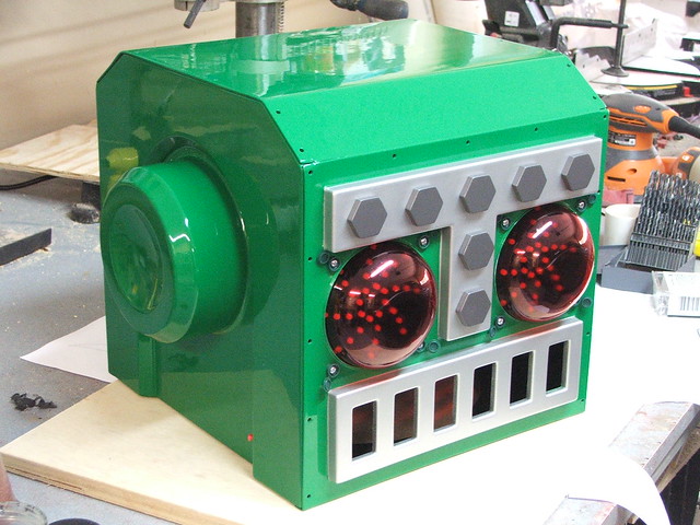
In this shot you can see the "little red button" on the lower front side of the helmet near the ear recess. All of the programming and control of the illumination board is done through this button. You can change animations, speed up or slow down, turn on power saver mode, etc.
The last step after re-mounting all of the components was to add the rivets to the seams to strengthen the structure a bit.
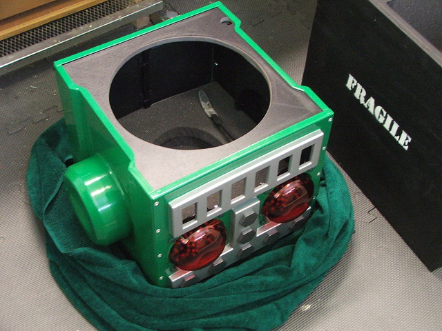
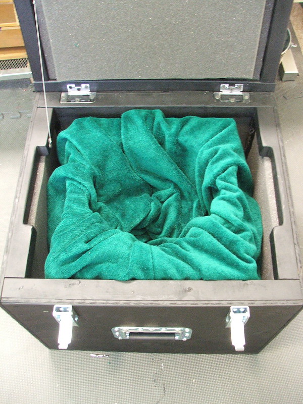
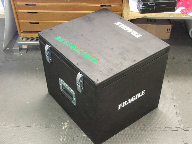
To make shipping and transporting this bucket easier and safer, I also built a custom shipping crate for it. My friend Cathy over at God Save the Queen Fashions even had some scrap green terrycloth around to make a protective shipping sack to further protect the paint and finish. The crate weighs about 10x what the helmet does, but it's really secure in there!
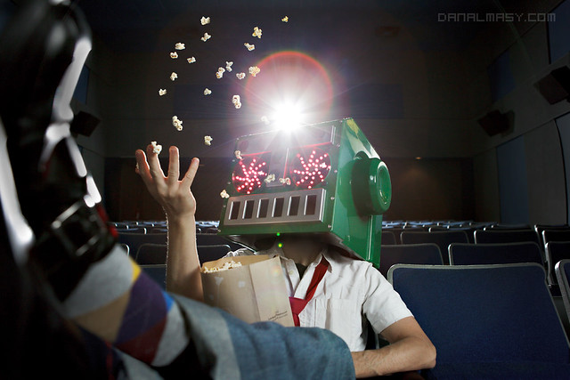
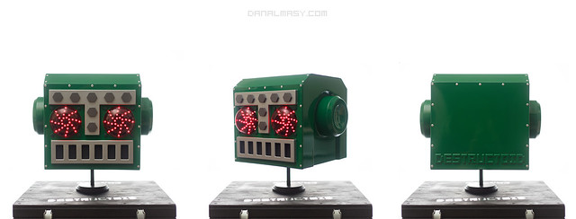
The final result! Thanks (again!) to my friend Dan Almasy for doing the great photography here.
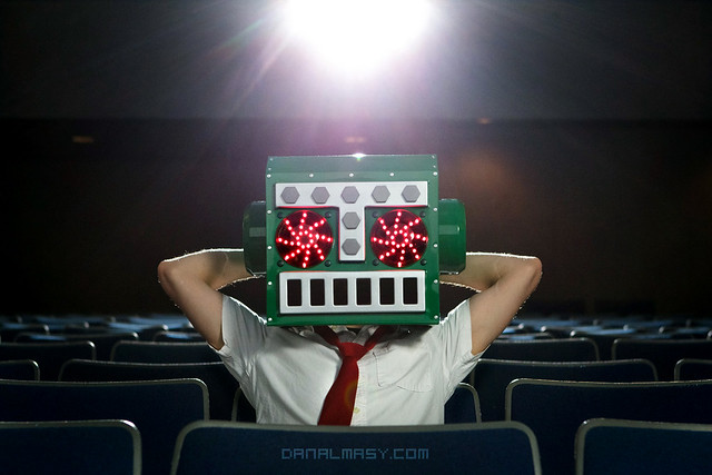
The finished piece weighs just over 3lbs and is quite comfortable to wear. There's a foam pad at the top of the helmet and it is secured to the wearer's head with an adjustable chin strap.
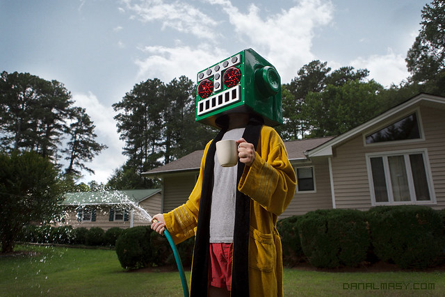
I really recommend you check out the high res version of the pic below - this shows off the finished result really well!
Thanks for reading, and if you'd like to see more higher resolution shots of the process, check out my Flickr page.
7 comments:
Nice project !
Very, very impressive. Amazing work!
Thanks for sharing, I learn a lot. I'm a electronic student and a design fan so I really like the making process :D
So cool =D
Stunning simulation of metal :О
I just loved the photos at the end lol, after all that hard work, it was used and hopefully will be used long afterwards brilliantly.
You made your own vaccuum former?! Kudos for engineering skill there!
Post a Comment